| David L O Smith - Home |
LMS Class 5P5F 4-6-0 'Black Five'LMS Class 5XP 4-6-0 'Jubilee' |
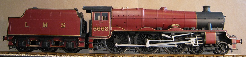
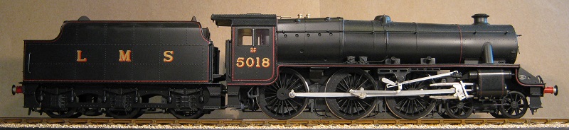
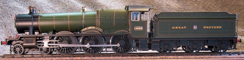
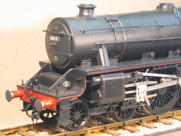
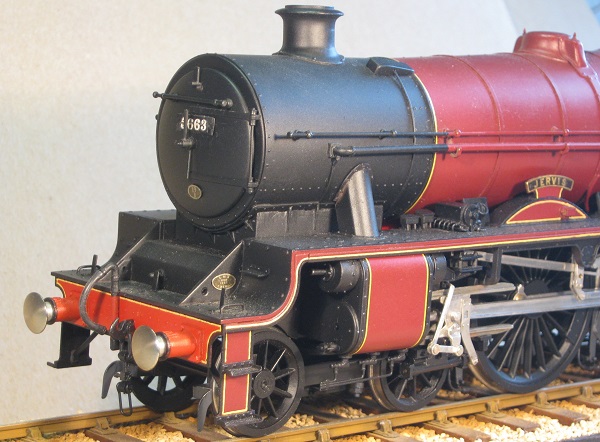
A 7mm scale (O Gauge) model of an 5P5F class mixed traffic locomotive No. 5018 and of 5XP class express passenger locomotive No. 5663 Jervis built by the LMS.
Earlier, I described how I reworked a LMS 8F and GWR Rood Ashton Hall, which are a similar RTR models by FineScaleBrass, so I here I describe only some more details and some of the differences. I have also described how I built a Stanier 3500 gallon tender for the Jubilee from an excellent kit that it is marketed by David Andrews. If you are interested in the more basic modifications and the principles that I have applied, please see the pages about my LMS 8F and Rood Ashton Hall.
| Go to: | Bogies | Radius Rods | Springs | Cylinder Pressure Relieve Valves | Motion | Injectors | Finished Models | Stanier 3500 Gallon Tender |
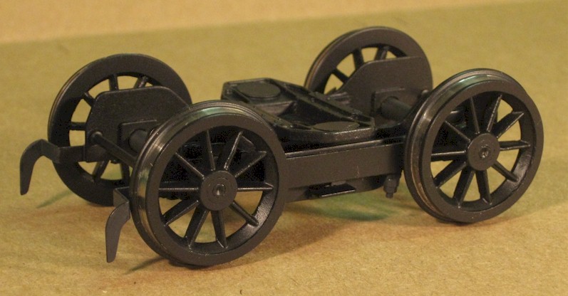
Bogies
Starting with the Stanier bogie, I found the rendition of the
by Finescale Brass basically quite acceptable:
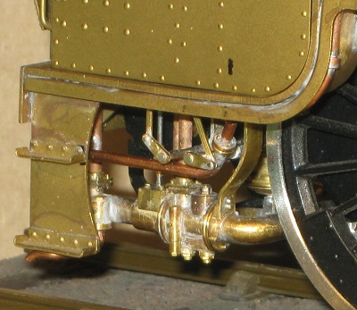
However, I did not like the heavy round stretcher, which is rather prominent at the front, the lack of spring detail nor the absence of the outer compensation beam. A few sessions in the workshop produced some modifications, which may easily be seen (below) as they are unpainted.
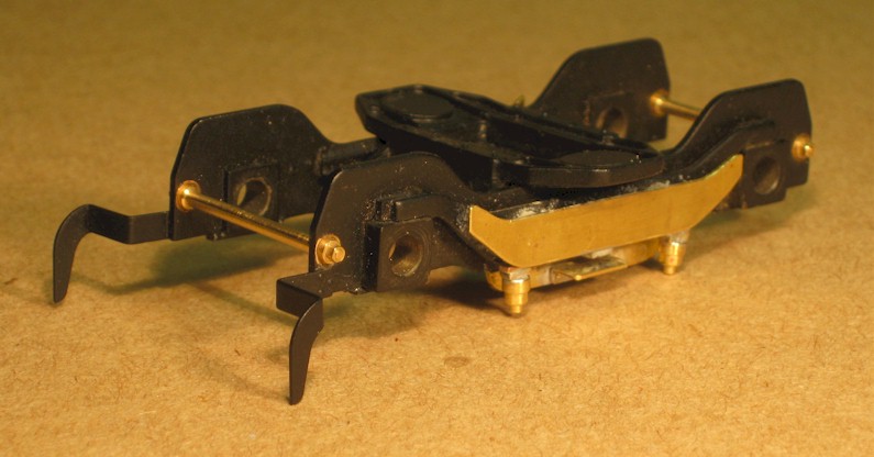
Painted and reassembled, the bogie looks more like something that Stanier would recognise.
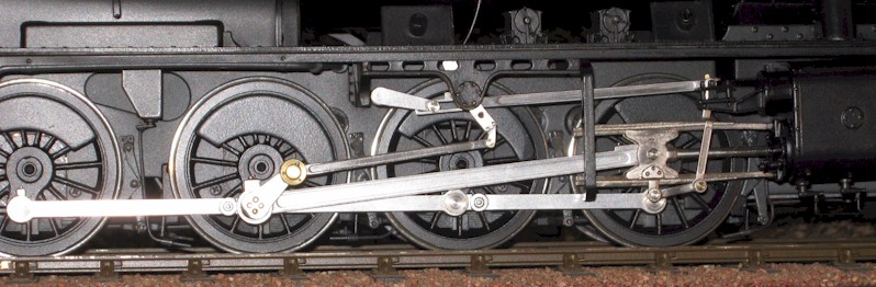
Radius Rods
Exactly as for the 8F, I reworked the radius rods (aka valve
rods) by adding a rearward extension with a slot to replace the simple hole so
that, when they are lowered in their expansion links to move the loco out of
mid-gear, they reciprocate a little, which is rather pleasing. Below is the
arrangement on my 8F.
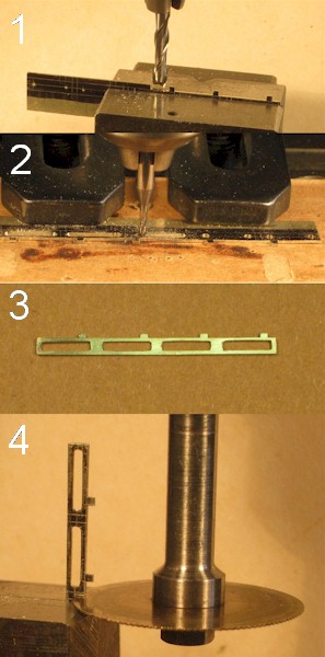
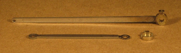
| Four extension parts were needed so I milled them out of a
piece of waste 0.5mm thick nickel silver etched sheet.
In the photograph (right):
|
|
The extensions are silver soldered onto the shortened rod, the whole cleaned up and tinned all over to represent steel (below). There is a step at the join (and it’s perfect round the back!) but this is of little consequence as it will be hidden within the expansion link support bracket.
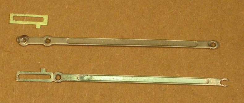
Component parts (above) and a completed radius rod (below)
Springs
I added some dummy springs beneath the keeper plates, which included making a
new gearbox cover plate. The arrangement on the leading and training axles
of the Jubilee as supplied (below); the keeper that retains the hornblock
(with ball bearing within) is retained by two screws.
On the left (below) are two spring castings (actually destined for the Black Five) from JPL Models, in the centre are two castings for the Jubilee that have been cleaned up and machined ready to be soldered onto a U-shaped bracket, as shewn on the right.
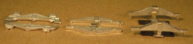
The end result
The gearbox cover plate, as supplied (below), also covers the screws that retain the keepers and it will foul the exhaust steam ejector supply pipe that will be screwed to a frame stretcher, which is also covered, so I made a new cover that incorporates springs and the keepers.
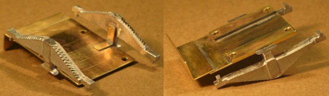
Replacement cover inverted (left) and correct way up
Replacement gear cover fitted
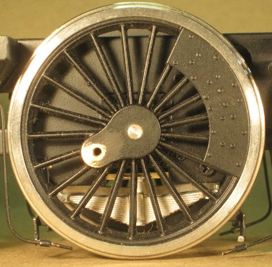
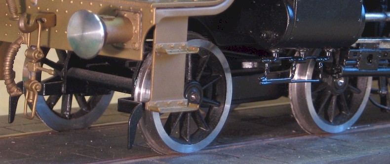
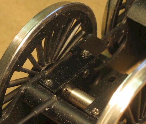
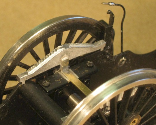
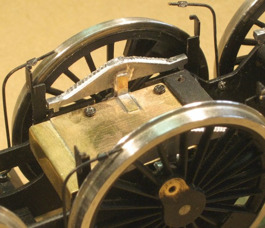
The springs are very obvious behind these Stanier wheels. I concede that they will be painted black – actually Floquil Dirty Black, which is a dark grey – but they will add a bit of detail in an area where it is rather sparse. It made a difference on my FineScaleBrass 8F and its wheels are much smaller and they may also be seen to good overall effect on my FineScaleBrass GWR Hall.
Cylinder Pressure
Relieve Valves
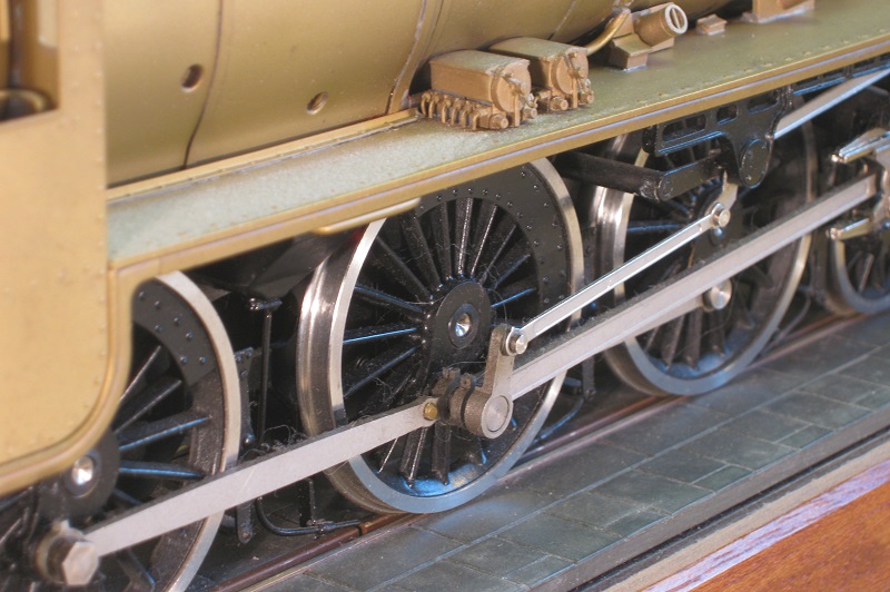
I decide next to tackle the cylinder pressure relieve valves. On the 8F,
these were represented by quite acceptable castings - they just need to be
turned through 90 degrees so that the oval flanges were oriented horizontally,
rather than vertically. On the Black Five and the Jubilee, however, the same
valves were represented by rather small, indistinct cylindrical castings that
were unprototypically outboard of the cylinder centre line, as may be seen in
the photograph at the beginning of the section about reworking
the bogie.
Of course, I could have bought castings (for £5, but I am not sure how many this is for) but I needed three pairs in all and I needed two pairs straight away, so I turned and milled them from brass rod.
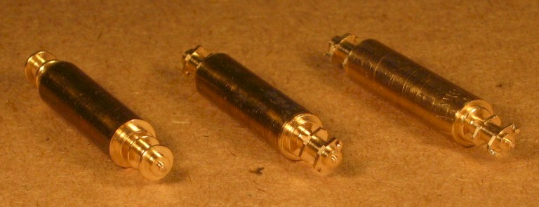
In the photograph (above), on the left is the first operation – turning; in the centre, the turned parts have been milled and two holes drilled for the flange bolts; on the right, the flange profiles have been finished off with a file and the ‘bolts’ soldered in. All that is needed now it to return the stock to the lathe, thin down the neck to form a 1mm diameter pin and to part-off.
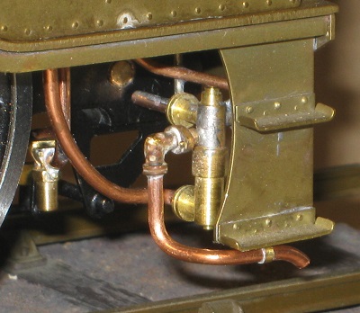
Whereas the paint on these models is applied evenly with a decent coverage for the most part, some areas (in the cab, particularly) receive rather too much paint and the fine detail is lost; the cylinder drain cocks and the associated pipework so suffered on these two models, as may be seen in the photograph at the beginning of the section about reworking the bogie.. The paint is relatively easily removed with Nitromors and scraping but one cylinder was already missing a drain pipe and on one the pipework was already rather bent (I have seen models in service with this problem) so I decided to replace the brass pipework with stiffer nickel silver wire and to fit the front clamps at the same time.
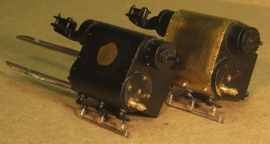
In the photograph (above), the right hand cylinder assembly from the Jubilee is in front and that from the Black Five is behind. On each cylinders may be seen i) the new pressure relief valve that is fitted on the centre line of the cylinder, with the former locating hole plugged, ii) the prominent central nut and stud in the cylinder head that protrudes through the outer cylinder cover, and iii) the replacement pipework from the cylinder drain cocks, along with a clamp.
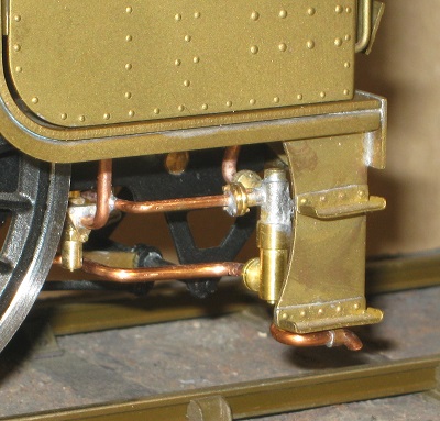
On the Jubilee cylinder assembly may also be seen four bolts (at 12, 3, 6 and 9 o’clock) that retain the cylinder cover, as they were absent from the model (although the Black Five had them, correctly oriented at 45 degrees to those on the Jubilee). On the Black Five cylinder assembly may also be seen two of the three plugs towards the bottom of the cylinder that I believe are removed to see the exact position of the piston whilst the valve are being set (but please correct me if you know). In both cases, my chosen models needed cylinder wrappers without the circular inspection covers in the sides. I was easily able to remove the covers on the Jubilee and then to feather away the edges of the paint. My Black Five had no cover on its left hand cylinder wrapper but it did have one on the right; I removed it but the paint was not adhering well and it was impossible to feather the edge satisfactorily, so I removed all the flaking paint from the wrapper by gently scraping.
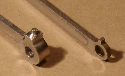
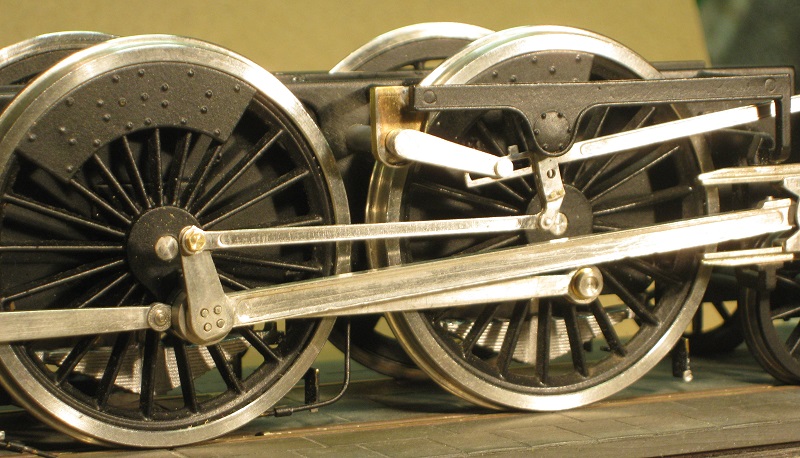
As I have mentioned before, I consider that the motion and other ‘lower works’ rather let down these excellent models. A case in point is the rods that, on the prototype, are not two-dimensional stampings but have thick bosses, particularly at the big end of the connecting rods.
In the photograph (above), I have sawn off the stamped big end of the connecting rod (top) and silver soldered on a more substantial item from nickel silver; the hole in the top will take a short piece of brass wire to represent the top of the oil reservoir and cork.
|
In close-up, a decently substantial bigend (left) may be clearly seen to be an improvement over the original two-dimensional stamping. |
|
Similarly, I made a more substantial centre boss for the coupling rod (bottom) but this will surround the original boss, rather than replace it. In this way, the centre distance between the holes in the coupling rod is preserved. As this is a leading rod, the leading boss will not be thickened but I have milled off the top to allow a more substantial representation of the oil reservoir to be silver soldered on. On the rear rods, I silver soldered a thickening disc on the front of the rear bosses before milling a flat on top for the oil reservoirs.
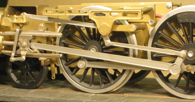
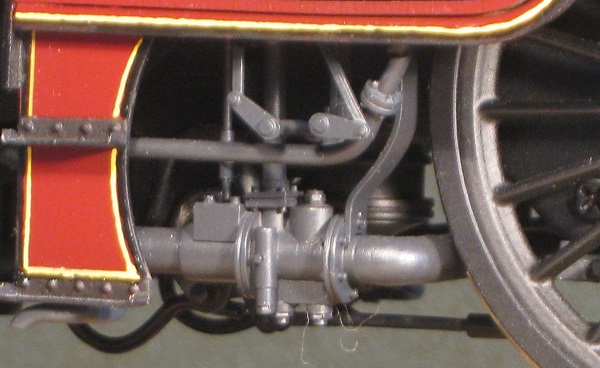
A detail photograph (above) of a part-built, factory second Black Five illustrates the relatively primitive representation of the motion but the improvements that may be made are shewn in the photographs (below).
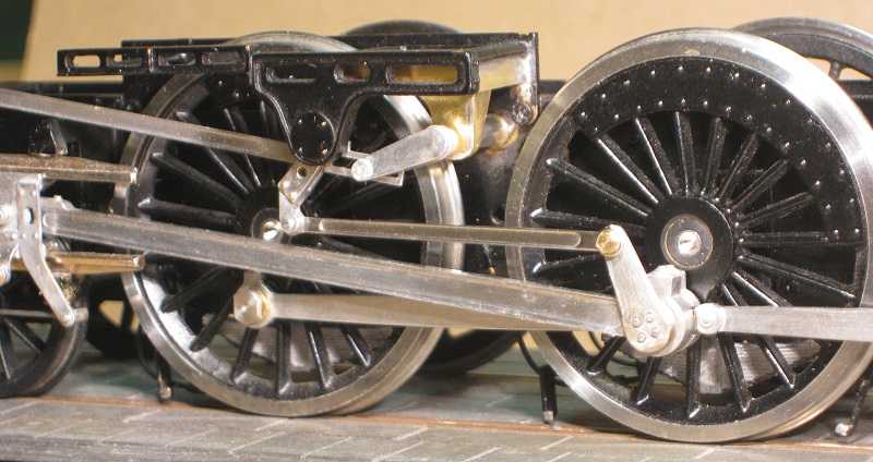
Black Five
Jubilee
Comparing the last two photographs with the one above them, I am not sure if there is any particular modification that has made the improvement but I would pick out the new return cranks and the expansion links as quite obvious. Neither of these was especially difficult (given that I had already done it once for the 8F) but it involved careful marking out, cutting out, cleaning up and soldering of parts from nickel silver.
The more accurate expansion links, along with the extended and slotted radius rods (aka the valve rods) that I described earlier, allow the radius rods to be lowered in the expansion link by the lifting arms so that they reciprocated slightly, which is rather pleasing as well as looking more authentic.
The original lifting arms disappeared behind the expansion link trunions and they appear to be supported in fresh air but a suitable bracket (in brass) to support the reversing shafts and shorter lifting arms that engage with the slot in the rear of the radius rods improve the look of all this.
Other small details, which I devised originally for the 8F, include nickel silver strips on the tops and bottoms of the connecting rods to give them a bit more presence and a reworking of the crankpins with bushes and retaining screws. I also made more plausible looking knuckle joints in the trailing coupling rods.
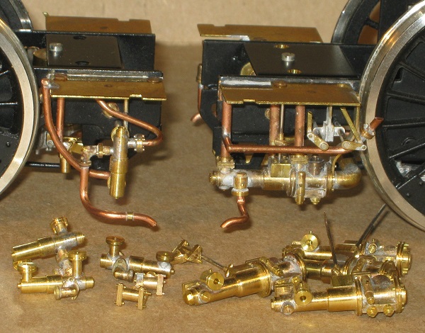
Injectors
I mentioned, when I made the injectors for my 8F, that
I made a few spares because I knew that I was going to need them. In
the photograph (below) is a live steam injector and vacuum line moisture
trap fitted to the Black Five (left) and an exhaust steam injector fitted
to the Jubilee (right), with a few spares for future locomotive
construction lying in front.
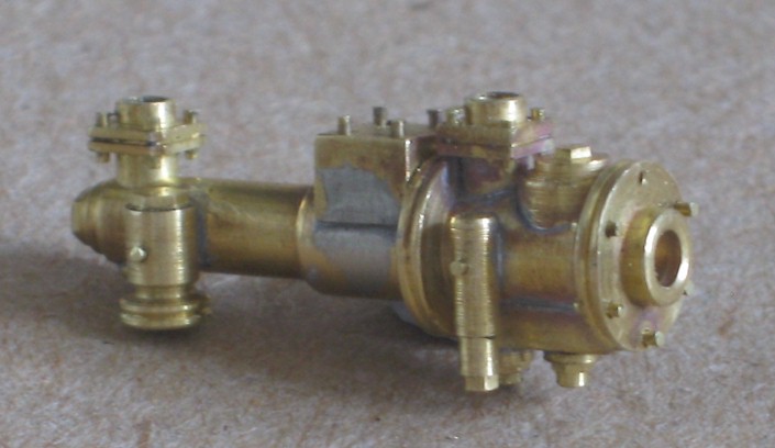
From my description of reworking my 8F here is a close-up photograph of one of these fabricated injectors.
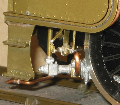 |
The Davies & Metcalfe exhaust steam injector on a Black Five lies at an angle below the cab (left), where it is not very visible, so I used the white metal casting from my recently completed British Legion, on which I used one of my home-grown variety as it will be quite prominent there, as it is on a Jubilee (right). |
 |
|
|
The live steam injectors lie rather coyly behind the driver’s step on both the Black Five (left) and on the Jubilee (right) but I do think that they are worth making decently. |
|
 |
 |
|
Black Five No. 5018 |
Jubilee No. 5663 Jervis |
The exhaust steam injector on the fireman's side of the Jubilee