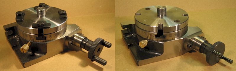
Before (left) and after (right)
| David L O Smith - Home |
Plain and Tilting Rotary Tables for Use with a Unimat |
Before (left) and after (right)
I describe here how I modified a small rotary table to make it more in the Unimat style and also to make fitting the adaptor for Unimat chucks easy and repeatable without the need to re-centre it each time it is replaced.
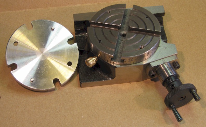
As purchased
As delivered, the rotary table is perfectly functional and the only practical drawback that I could see was that there is no way of precisely locating the adaptor for Unimat chucks (a circular plate with a 14mm stud that is clamped to the table with four hexagon-head screws, washer plates and T-nuts) so that it runs true with the centre of the table. It seemed to me that it was a simple matter to set the adaptor to run true just once, tighten the four clamps and then to drill four holes through the adaptor into the ‘lands’ of the table; two to take locating dowels and two to take socket headed screws to hold the adaptor down. However, before I did this, I decide to work on the cosmetic aspects.
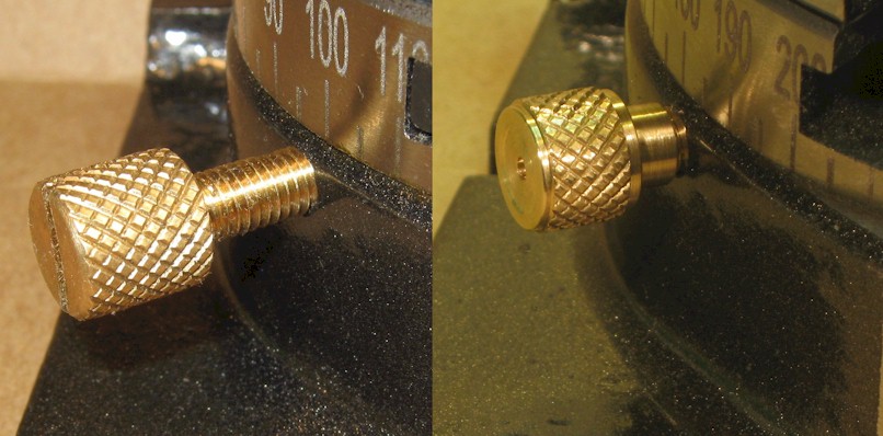
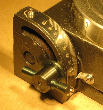
The original locking knob (left) looked a bit clumsy to me so a simple bit of turning and fitting a screwed collar over the exposed thread produce a neater job (right).
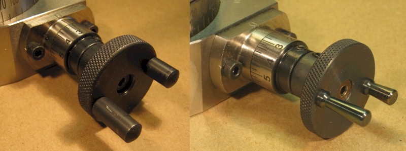
Similarly, the original angle adjusting wheel (left) looked a bit ‘heavy industrial’ compared to the Unimat fittings so I turned down the two handles and removed a couple of millimetres from the front of the wheel to make something just as functional but rather lighter (right) and more in keeping with the Unimat milling machine that I am most likely to use it on.
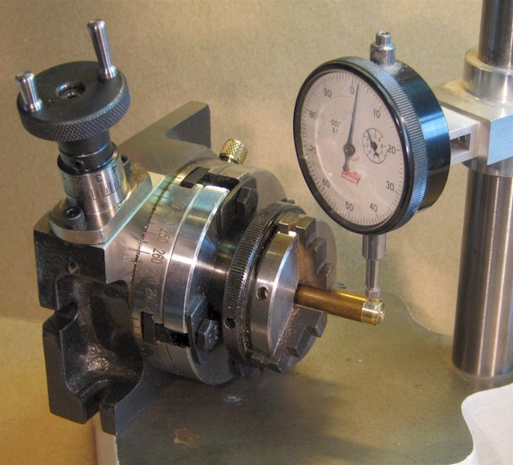
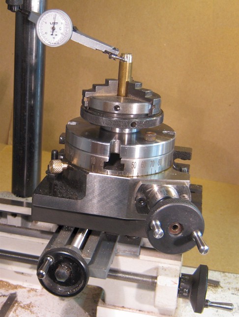
To centre the Unimat adaptor, I chucked a piece of brass bar and turned a short section at the end and then mounted the chuck on the adaptor, which was lightly clamped to the table. I placed the whole assembly on the comparator table (but there are many other ways I could have done it) so that I could rotate the table and tap the adaptor, to adjust it in the slots, until the ‘clock’ showed that the bar was running true (within 1 thou, 0.025mm), then I nipped the clamps up tight and checked that the bar was still running true.
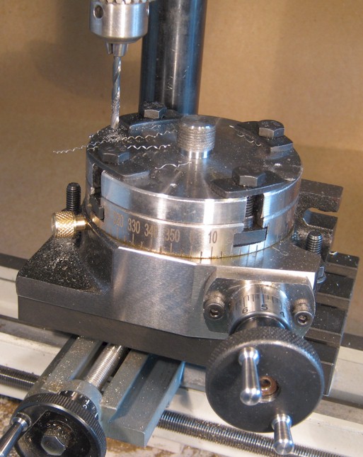
Having clamped the rotary table to the Unimat milling machine, I drilled two holes so that they could be reamed 0.124” and the other two I drilled 4.2mm, tapping size for M5. Once unclamped, the tapping holes in the adaptor were opened out to 5mm clearance and counter-bored for socket head screws, and the 0.124” holes were reamed out to 0.125” from below to within about 3mm of the top surface. The holes in the table were reamed out to 0.125” and tapped M5, as appropriate.
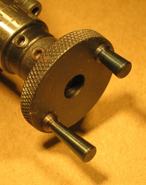
It was a simple matter to turn two precision-ground silver steel pins and press them into the reamed holes in the adaptor.
The proof of the pudding … is in the checking and I was reasonably pleased to discover that the ‘clock’ (this time set up in the chuck of the milling machine) showed that the eccentricity (runout) was no more than 1.25 thou (0.032mm); if I ever need anything closer than this, I shall just have to set it up in the 4-jaw chuck and clock it true, which is not bad practice anyway.
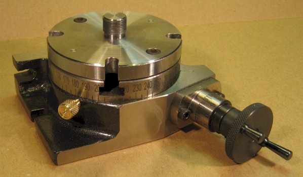
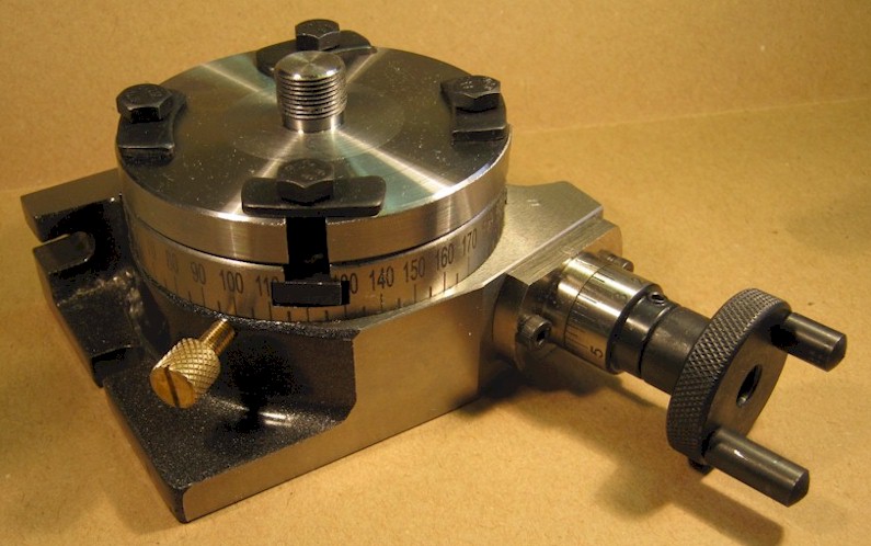
The finished job
I originally prepared this write-up for a Gauge 0 Guild forum topic 'In the DLOS Workshop'.
...oooOOOooo...
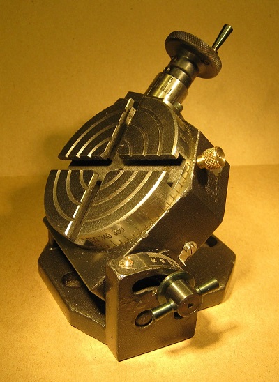
Later, when a tilting table became available from the same manufacturer, I made similar modifications to improve its appearance and to make it more in the style of the Unimat.
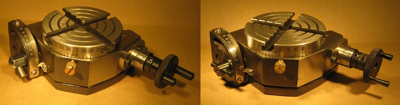
Before (left) and after (right)
As for the plain rotary table, I reduced the size of the rotary clamping screw and the handles on the adjusting wheel (left). In addition, I modified the tilting clamping screw to have two handles, of a finer profile, and I tidied up the scale (right).
|
|
|
The finished job
Back to Workshop Machine Tools